How to disassemble the Bosch gbh 2 24 rotary hammer
How to Lubricate and Assemble a Bosch 2-26 Peorator
The principle of operation of the Bosch 2-26 is the same as that of the famous brands. The rotating rotor transmits torque to the intermediate shaft of the mechanical unit, simultaneously transmitting, via the roller bearing, progressive motion to the hammer mechanism of the hammer and the impact pulse. The torque is transmitted to the working tool with a progressive impact pulse. This principle is realized in all gyroplanters.
But different companies that produce peorators have their own design features.
Bosch rotators are considered the best in their segment of power tools. But nothing lasts forever.
If your Bosch 2-20, 2-24, 2-26 has stopped working, you can repair it with your own hands. You only need basic locksmith skills and a little electrical know-how. One more important detail, the design of the Bosch torches is so simple that it is not difficult to repair them.
When repairing power tools, including Bosch rotary table saws, always follow safe working practices when operating a power tool.
To facilitate the repair, disassembly and reassembly of the Bosch Peorator, study the assembly diagram of the tool:
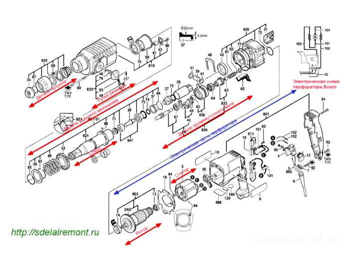
Diagram of the Bosch 2-26 torch
Any disassembly of the Bosch 2-26 torch begins after you have inspected it, tried it out and found the cause of the malfunction.
Bosch 2-26 Disassembly Video
Disassembly procedure for the Bosch 2-26 Peorator
Because the order of disassembly of the Bosch 2-20; 2-24; 2-26 is almost the same, let’s examine the disassembly sequence on the example of the Bosch 2-26.
The disassembly of the Bosch GBH 2-26 dre begins with the disassembly of the quick-release chuck.
Disassembling the quick-release chuck
There are two types of chucks most commonly used in Bosch rotary tools: SDS-plus chucks and SDS-max chucks. The difference between them is in the principle of clamping the tail part of the working body.
The design of the Bosch torch chuck differs in the construction of the tool’s seating rods depending on the SDS-plus or SDS-max model. In addition to the above chuck types there are SDS-top, SDS-quick chucks.
The difference between the chuck attachment assemblies
The disassembly procedure for the Bosch 2-26 chuck is simple:
- remove the rubber tip pos.34;
- Remove retaining ring pos.87;
- Remove the steel washer pos.833;
- take out the conical spring pos.833;
- carefully, so as not to lose it, using a magnet, take out the barrel balls pos.89.
SDS-plus chuck
Carefully examine all parts of the chuck.
SDS-plus quick-release chuck disassembled
SDS-plus chucks are developed especially for the drilling tools. tool shank diameter 10 mm, working tool length between 110 mm and 1000 mm. Drill diameter is in the range of 426 mm.
How to remove the mode switch
Stand the chuck on its side and remove the reversing lever pos.832.
First turn the switch to the “Drill” position, press it with a screwdriver as far as it will go into the red end of the switch and turn it counterclockwise by an angle of 70º.
Pull the rotary switch handle out of the housing by rocking it.
Disassembly of the striker assembly
Standing the Bosch 2-26 firing pin vertically on the handle, unscrew the four screws pos.90 holding the cover of the firing pin.
Press on the shaft end of the beater and remove the cover. Black plastic cover.
Now remove the barrel, pos.821 and intermediate shaft pos.826. They are not secured in any way.
Next, use a screwdriver to remove the bracket pos.48 rolling bearing pos.830. By the way, in a simple way it is called “drunken bearing”. The following are removed one by one: sleeve, pos.26 and the “drunken bearing”.
Got to the drunken bearing
Disassembly of the perforator barrel assembly
- Disassembly of the Bosch perforator barrel assembly begins at the cavity side by removing the cylinder pos.26 with the striker pos.27;
- From the cavity you must take out the beater assembly;
- From the side of the chuck shaft remove the locking ring pos.85, steel ring pos.38 and another retaining ring pos.85;
- remove spur gear, pos.22.
Tumbler Assembly, Intermediate Shaft and Drunk Bearing
Disassembly of the cylinder
The striker, pos.27 from which the rubber ring must be removed pos.73. The rubber parts must be replaced during any disassembly.
Hinge pos.29 and two flat washers pos.41.
Disassembly of intermediate shaft
Intermediate shaft is disassembled by removing the shaft pos.24 and pulling it out of the housing pos.77 of the “drunken bearing” is inserted inside the cylinder.
Bearings are removed with pullers or manually with a tool.
Disassembly procedure of the Bosch 2-26
Since the order of disassembly of the Bosch 2-20; 2-24; 2-26 is practically the same, let’s examine the disassembly order on the example of the Bosch 2-26.
Disassembly of the Bosch GBH 2-26 dre begins with the disassembly of the quick-release chuck.
Disassembly of quick release chuck
There are two types of chucks most commonly used in Bosch peorators: SDS-plus chucks and SDS-max chucks. The difference between them is in the principle of clamping the tail end of the working body.
The Bosch chuck design differs depending on the SDS-plus or SDS-max model in terms of the tool drive shafts. There are SDS-top, SDS-quick chucks in addition to the above mentioned types.
The difference between the chuck mounts
The disassembly procedure for the Bosch 2-26 chuck is simple:
- Remove the rubber nipple pos.34;
- Take out retaining ring pos.87;
- remove the steel washer pos.833;
- remove the conical spring pos.833;
- carefully, so as not to lose it, using a magnet, take out the barrel balls pos.89.
SDS-plus chuck
Carefully examine all the parts of the chuck.
SDS-plus quick-action chuck, exploded
SDS-plus chucks were designed specifically for drilling tools. Tool shank diameter is 10 mm, working tool length in the range of 1101000 mm. Drill diameter is in the range of 426 mm.
How to remove the mode switch
With the instrument sideways, remove the mode switch pos.832.
First turn the switch to the “Drill” position, press the screwdriver all the way to the face of the switch (red) and turn the switch counterclockwise by an angle of 70º.
Wiggle the switch handle and pull the switch handle out of the housing.
Disassembly of the hammer unit
Hold the Bosch 2-26 vertically on the handle and unscrew the four screws pos.90 holding the cover of the mechanical assembly body.
Press on the shaft end of the percussion mechanism and remove the cover. The cover is black plastic.
Now remove the barrel pos.821 and intermediate shaft pos.826. They are not fixed in any way.
Then use a screwdriver to remove the bracket pos.48 rolling bearing pos.830. By the way, it is simply called the “drunken bearing”. The following are removed one by one: cartridge case pos.26 and the “drunken bearing”.
Got to the drunken bearing
Firing pin assembly disassembly
- Disassembly of the Bosch perforator barrel assembly begins at the side of the cavity by taking out the cylinder pos.26 with beater pos.27;
- The boss assembly has to be taken out of the cavity;
- on the side of the chuck shaft remove retaining ring pos.85, steel ring pos.38 and one more circlip pos.85;
- remove the spur gear pos.22.
Firing mechanism assembly, intermediate shaft and drunken bearing
Disassembly of the cylinder
Inside the cylinder is the firing pin pos.27 cylinder, from which the rubber ring pos.73. Rubber parts must be replaced at all times during disassembly.
On the opposite end of the cylinder there is a pivot pos.29 and two flat washers pos.41.
Disassembly of the intermediate shaft
The intermediate shaft is disassembled by removing the shaft pos.24 and pulling out of the housing pos.77 “drunken bearing”.
The bearings can be removed with pullers or by hand, by means of a device.
How to prolong the service life of a Bosch rotary table
Bosch torches must be inspected and serviced at all times. In order to operate the torches properly, you must:
- Do not allow dust to enter the cooling holes (you may wear a plastic sock or use a vacuum cleaner);
- Grease drill shanks with special grease;
- Do not overheat the power tool (overheating causes the grease to crystallize and stop lubricating the rotating parts);
- Replace the rear rotor bearing every 6 months if operating intensively; Replace the carbon brushes after 70 hours;
- When drilling holes in the ceiling, turn the rotary table upside down and rotate it so that the grease flows back into position;
- After work it is obligatory to blow out with compressed air the insides of the torus;
- change the rubber sleeve on the chuck of the perforator more often;
- Do not allow the collector brushes to spark when idle;
- continuous operation time should not exceed 30 minutes;
- Do not use the “Punch” mode often.
When you begin repairing a Bosch 2-20, 2-24, and 2-26 peorator, refer to the lubrication chart for lubrication points and lubricants.
Bosch torch lubrication card
Several types of grease are used for the lubrication of Bosch torches, depending on the operating conditions of the assemblies and parts.
Four types of lubricants are used in Bosch torches:
- Grease 1615430001 for the gearbox and its cavity;
- Grease 1615430002- for gears, pendulum roller bearing, clutch;
- grease 1615430020. for bearings (FT1V26);
- SAE 20 W grease. for rubber products.
Greases differ in viscosity and consistency.
From Russian lubricants can be recommended greases under the ringing name “Zubr:
Domestic drill shank lubrication for Bosch rotary tools
8 bearings are used in Bosch rotators: three anti-friction bearings pos.13,14,67, a pendulum bearing (drunken bearing) and four needle bearings pos.60,61,62,63.
Bosch 2-26 schematic diagram in sectional view
Repair instructions. Replacing and connecting a torch button with a Makita 2450 as an example
Most Makita peorators (models HR2020, 2432, 2440, 2440F, 2450, 2455, 2475 and 2641) use a typical TG813TLB-1 series switch.
To inspect and/or replace them you need the following tools:
The procedure to repair/replace the trigger on a Makita 2450 is as follows:
Useful tips
It is not uncommon for even professional equipment to fail quickly. This is caused by the tool working with a significant overload on the electric motor. The power unit must not be allowed to overheat and periodic process pauses must be taken. Sometimes serious damage to the torch is the result of careless handling during use or storage.
After each use, the torch must be thoroughly cleaned of dust. Wipe not only the housing of the power tool but also the ventilation slots with a soft cloth or tissue.
Do not use the torch outdoors when it is raining or snowing.
Regularly inspect the carbon brushes, which are a responsible part of the electric circuit. they conduct current to the collector and in the process of operation gradually wear out and require replacement.
It is not necessary to buy non-original accessories of dubious quality that can lead to more significant damages.
Bosch Peorator Button Repair
The principle of operation of the Bosch 2-26 is no different from that of recognizable brands. The rotating rotor transmits the torque to the intermediate shaft of the mechanical unit, immediately transferring the translational motion via the roller bearing to the hammer mechanism of the rotor and the impulse of the hammer. The working tool receives a rotating torque with a progressive shock pulse. This principle is implemented in many penoscopes.
Different peorator companies have their own design features.
Bosch torches are considered to be the best in their sector of power tools. Alas, nothing is permanent.
If your Bosch 2-20, 2-24, 2-26 does not work, of course you can repair it at home. You need to have a simple locksmith’s skills and little understanding of electrical engineering. And another important detail, the design of the Bosch torch is so simple that it does not cause difficulties when carrying out repairs.
When repairing power tools, including the repair of Bosch torches, strictly follow safety procedures when working with power tools.
To facilitate the repair of your Bosch peorator, its disassembly and assembly, study the scheme of the tool’s assembly:
All disassembly of the Bosch 2-26 torque converter begins after you have inspected it, tried it out and found the circumstances of the failure.
Since the disassembly order of the Bosch 2-20; 2-24; 2-26 is actually similar, let’s examine the disassembly order on the example of the Bosch 2-26.
Disassembly of the Bosch GBH 2-26 dre chuck begins with the disassembly of the quick-release chuck.
Bosch rotary tools use two types of chucks for the most part: SDS-plus and SDS-max chucks. The difference of them is mainly the clamping of the tail part of the working body.
The Bosch chuck design differs depending on the SDS-plus or SDS-max model depending on the type of tool. Not counting the listed chuck types, there are SDS-top, SDS-quick chucks.
The difference between the elements of fastening chucks
The disassembly procedure for the Bosch 2-26 chucks is conventional:
- Remove the rubber nose pos.34;
- Take out the retaining ring pos.87;
- Remove the iron washer pos.833;
- Remove the conical spring pos.833;
- carefully, so as not to lose it, using a magnet, take out the barrel balls pos.89.
Carefully look at our customer remains chuck parts.
SDS-plus quick-action chuck unassembled
SDS-plus chucks were developed specifically for drilling tools. tool shank cross section is 10 mm, tool length in the range of 1101000 mm. Drill bit cross-section lies between 426 mm.
With the torch on its side, remove the mode switch pos.832.
At first turn the switch to “Drill” position, press with screwdriver on the butt-end of the switch (it is reddish) and turn the switch counterclockwise by an angle of 70º.
Wiggle the switch handle and pull the switch handle out of the housing.
With the Bosch Peorator 2-26 upright on the handle, unscrew the four screws pos.90 holding the cover of the body of the mechanical unit.
Push down on the flank of the pinch shaft and remove cover. Dark colored plastic cover.
Now it is necessary to remove the barrel pos.821 and intermediate shaft pos.826. They are not secured in any way.
Then using a screwdriver to remove the bracket pos.48 rolling bearing pos.830. When, in plain language it is called the “drunken bearing”. Remove in turn: cartridge case pos.26 and the “drunken bearing”.
- start disassembly of the Bosch torque arm assembly without familiar cavity by taking out the cylinder pos.26 with firing pin pos.27;
- The striker assembly must be removed from the cavity;
- the unfamiliar cartridge shaft remove the retaining ring pos.85, iron ring pos.38 additional locking ring pos.85;
- remove the spur gear pos.22.
Tumbler assembly, intermediate shaft and intoxicated bearing
The striker pos.27, from which the rubber ring pos.73. In any disassembly, the rubber parts are replaced immediately.
At the opposite end of the cylinder there is a pivot pos.29 and two flat washers pos.41.
The intermediate shaft can be disassembled by removing the shaft pos.24 and pulling the pos.77 “drunken bearing”.
Bearings can be removed with pullers or manually with a device.
Bosch torches are very reliable. But there are failures that are practically unheard of in practice. Below is one of their number.
If the peorator does not chisel, but allows you to drill, the most possible reason is the destruction of the “drunken bearing”. This fault is rare and difficult to find.
You don’t need to go to a repair shop to fix it. Any slightest know-how of mechanics can clear up such a failure.
First you need to disassemble the Bosch oven to the intermediate shaft. The disassembly procedure is shown above.
After removing the intermediate shaft, you will get to the “drunk bearing”. A damaged roller bearing is indicated by a broken cage, scattered balls and pieces of the cage.
Take out the bearing, remove the dirt, which is left for our customer to do parts of the ruined mechanism.
buy a new “drunken bearing”, and, having lubricated the parts with the latest grease, carry out the replacement and assembly, in the sequence reverse of the steps of disassembly.
Disassembly of the Bosch 2-26 peorator, its electronic part, begins with the removal of the back cover on the peorator handle by removing the three screws.
The next step is to pull out the reversing switch.
Rotate it into neutral position and lift it personally. Pull out the reversing switch.
To remove the stator cover you need, clutching the mechanical unit in the right hand, in the left hand stator housing, drag them in different directions, rocking.
Separating the impactor unit with rotor and stator
To separate the rotor from the mechanical unit it is enough to drag these parts in different directions. The rotor is fixed in the mechanical unit by a small helical gear inserted in contact with the large helical gear of the mechanical unit.
Cartridge disassembly and repair
One of the most frequent breakages faced by the owners of peorator is a cartridge failure. To disassemble it you will need the following tools: screwdriver, hammer, pliers and wrench.
First find the rubber sleeve on the end face and remove it and the circlip. After that you will have access to the working clutch, which must be displaced and remove another locking ring. To unclamp the rings you can use a flat-blade screwdriver. The next step is to remove the spring and retaining balls. Now you need to remove the chuck, to do this, you can use a vice and clamp in them, take a spanner and flats to rotate the spindle.
In case the chuck is loose while working with the rotary tool, it may mean that the chuck body in the place of attachment is not in good condition. To fix this problem it is enough to replace the retaining ring with a new one.
There are cases when during the use the drill comes out of the chuck. Then disassemble the cartridge and determine what could be the cause. Look at the following parts: balls, stop ring and fixing spring. If any of them is damaged, you need to replace it, then the problem will be solved.
If it is clear from disassembly of the cartridge that the internal cylinder is defective, the cartridge must be replaced in its entirety because it cannot be repaired. In this case, you can take out all the parts that have not yet worn out from the old chuck, they may be useful in the future if some of these components wear out in the new chuck.
After the repair, it is important not to put heavy loads on the tool for the first time to check the functionality of the tool.
Assembling the mechanical part of the Bosch 2-26 peorator
Before assembling the mechanical part, check the presence of new rubber sealing rings, the integrity of all parts, and the presence of lubricants according to the lubrication chart above.
Assembling scheme of the mechanical unit assembly
Intermediate shaft assembly
Intermediate shaft assembly pos.826 begin with mounting on the shaft of the bearing pos.67, clutch coupling pos.62 and drunken bearing pos.830.
Shaft is fitted with a toothed sleeve pos.823, needle bearing pos.63, compression spring pos.81, support sleeve pos.65.
The intermediate shaft assembly is inserted into the inner housing pos.820 and locked by clamping bracket pos.48.
Intermediate shaft assembly
Assembling the percussion shaft assembly
Assembling the firing pin assembly begins with placing on the shaft of the barrel, pos.821 of the spur gear pos.22, conical spring pos.80, locking rings pos.85 and the steel ring pos.38.
Installed pinion pos.22 on the shaft of the barrel is secured by a roller pos.88, preventing the pinion from turning.
On the opposite side of the shaft cavity the striker pos.847 assembly and percussion piston pos.26 complete.
Bocsh striker assembly diagram and procedure
Beater assembly begins with installation of rubber O-rings pos. 74.75, scraper pos.71. Insert the assembled striker firmly into the cavity of the table.
Assembly of the striker piston begins with installation of two washers pos.41. To keep the washers in the piston groove, grease the groove surfaces. It remains to install the piston pin pos.29. Place the striker pos. 820 71 into the inner cavity of the striker piston.27 and insert the entire assembly into the cavity of the firing pin barrel.
Schematic diagram of the Bosch percussion mechanism barrel assembly
Install the striker barrel and intermediate shaft in the inner casing pos.820.
Assemble the mechanical assembly and rotor
Attach the rotor to the assembled mechanical unit. Put the gears of the rotor and the striker assembly firmly inside each other. To install the rotor in the mechanical assembly of the peorator, you need to insert the rotor helical gear in the inner housing until it contacts the helical large pinion of the intermediate shaft. After assembly turn the rotor, checking for smooth rotation.
Connection of the rotor and the percussion barrel mechanism
After assembly the mechanical assembly is closed by means of the black plastic cover pos.819. Cover is fastened with four screws pos.90, by installing a rubber gasket pos.77. Always grease the rubber sealing ring with SAE 20 W grease before mounting.
Now it remains to connect the stator housing (green) with the mechanical housing (black). Screw housings together with 4 screws.
And as a last step the carbon brushes are installed pos.811 into the brush holders of the reversing switch pos.16. Push button pos.4 turns regulator.
Wires from stator windings are connected to the button pos.101, 102, power cable pos.806.
Turn the shaft of the percussion mechanism (first manually and then energized) and make sure that the rotor rotates smoothly and the brushes do not interfere with its movement, evenly touching the lamellae of the collector. The sparks in the area of the brushes do not have a tail, but sparks evenly over the whole width of the working part.
Still need to close the cover pos.41 two screws pos.77.
Installing the Mode Switch Knob
To install the mode switch knob, first click the mode switch knob in the direction of the arrow on the keypad.832 The Bosch 2-26 should be placed on its side.
Setting the Mode Switch
Assembled mode switch handle pos.832 must be installed in the housing so that the red handle button is parallel to the handle.
Knob is turned clockwise until it reaches the “drilling” position. The “click” sound is heard. The knob is inserted.
Be sure to test the operation of the mode switch by turning it to the correct position and engaging the lever for each mode.
Assembling the quick-release chuck
Bosch rotary tools use SDS-plus type chucks.
They differ in terms of design by tool clamping.
The assembly of the chucks peoratora is made after repairing the chuck, replacing the destroyed part.
Before assembling the chuck it is absolutely necessary to check the fixing balls. There must not be any traces of corrosion and their diameter must not differ from the nominal by more than 0.01 mm.
The assembly sequence for the quick-release chuck has been described on our website many times.
The quality of assembly of a quick-release chuck is determined by its operability. Insert any tool with a suitable tool shank into the chuck. Hold the core bit with your hand and try to pull it out of the chuck with your weight. If they do not, the functioning of the cartridge is considered to be reliable.
That’s it. The Bosch 2-26 is assembled. The assembly of the 2-20, 2-24 chucks is virtually the same except for some minor details that do not affect the assembly process.
What you need to know about repairing peorators?
Undoubtedly, the owners of such expensive equipment want their devices to be of high quality and do their job 100%. Above all, proper use of the tool will protect you from serious damage, which we’ll talk about later. And, of course, the timely repair of the device. At the same time, any small malfunction should already be cause for concern and preparation for repair.
- Unstable operation of the peorator in working mode;
- Appearance of strange sounds when you turn on the shock;
- The smell of burning;
- Peorator is not clogged, although there is no obvious reason for this.
When something like this has happened to your equipment, it’s time to fix it
Like any such job, it requires caution, understanding the cause of failure and knowing how to deal with it. And your first step in repair
Analyze the instrument for its components. For many, even this step is complicated, so you need to know everything with nuances. How, what and why!
READ Error ce on Bosch boiler how to fix
The rules of operation or how to protect the device from breakage
To keep your power steering machine long and effective, just follow a few simple rules. In particular:
- It is inadvisable to press too hard on the tool during work as, at least, this is not necessary and, moreover, if there is excessive pressure, the tool breaks down faster.
- Do not allow the rotary axis to run dry.
- When working on porous materials it is wise to switch off the shock absorber. When working with particularly hard materials, it is advisable to use a lubricant.
- Especially during continuous operation, the heat build-up in the housing must be monitored, especially in the area in which the gear unit is installed. If there is noticeable heat build-up, stop work and wait for it to cool down. Water must not be used for cooling as it may damage parts of the gearbox.
- Work with the tool should be carried out in the following mode. at least 10 minutes of break after half an hour of work.
Disassembly of the starter motor and removing the cartridge
, At first we need to get it rightdisassemble. And we begin by disassembling the cartridge.
- Remove the rubber tip and retaining ring;
- Remove the washer and conical spring;
- Take out the side balls (better with a magnet);
- We put the mode lever in the position equal to the largest one and remove the switch handle. Secure the position;
- Remove the back cover on the handle and the motor brush;
- Unscrew 4 screws near the auger to remove the front cover;
- Remove the barrel and shaft, and using a screwdriver, remove the bracket and bearing;
- Open the rear cover and take out the reversing switch;
- Remove the rotor, why unscrew the fasteners and disconnect the terminals from the starter, which must also be removed by removing the protective cover.
Consider options in which the peorator drills but does not chisel
The locking roller does not fix the huge pinion of the shaft of the barrel
Large pinion pos.22 is attached to the shaft of the barrel pos.01 roller pos.88, is pressed to the shaft shoulder by the conical spring pos.80 and secured with the retaining ring pos.85.
Slackening of the conical spring force pos.80, destruction of the retaining ring pos.85, locking roller drop out pos.88.
Pinion pos.22 on the shaft pos.01 of the barrel pos.821 Pinion assembly
Unusual fault of the Bosch torque converter
are very reliable. But there are malfunctions that are virtually invisible in practice. The following is one of them.
How to disassemble the Bosch 2-26 torch
Since the order of disassembly of the Bosch 2-20; 2-24; 2-26 is practically similar, let us examine the disassembly sequence on the example of the Bosch 2-26.
Disassembly of the Bosch GBH 2-26 dre begins with the disassembly of the quick-release chuck.
Let’s look at the variants in which the peorator does not drill or chisel
The intermediate shaft is disassembled by removing the shaft pos.24 and out of the housing pos.77 “drunken bearing”.
Bearings are removed by pullers or manually, with a device.
The engine stops chiseling, but drills
Nor does it chisel under load or at idle for the following reasons:
- Rubber rings of the striker, striker and piston are worn;
- The cage of the antifriction bearing collapsed;
- The cylinder is destroyed, the striker barrel is collapsed;
- the splines of the clutch installed on the intermediate shaft are sheared;
Construction of the intermediate shaft of the Bosch 2-24 peorator
The countershaft of the Bosch 2-24 consist of a roller bearing unit pos.830, clutch pos.823, shift part pos.44. In most cases the clutch clutch fails. The teeth in it are wearing out. Repair of the clutch consists in correction of a profile of a tooth of meshing in the clutch and on the intermediate shaft.
Design features of the Bosch torch 2-26
2-26 you should begin by familiarizing yourself with the design features of the tool you are setting up. The operating principle of the Bosch 2-24 is identical to that of the Bosch 2-26.
Rotation is transmitted from the rotor shaft, through the intermediate shaft, to the striker shaft. Immediately, an intoxicated bearing attached to the intermediate shaft transmits reciprocating motion to the percussion piston.
there are three modes of operation for the accelerator: drilling with impact, drilling without impact, impact.
Rotor helical gear pos.803 transmits the torque to the helical gear of the intermediate shaft pos.823.
The intermediate shaft is similar to the shaft in the design of the Bosch 2-24 and is interchangeable with the parts included in the intermediate shaft Bosch
2-24, 2-26. Disassembly guide for Bosch torch.
What is the reason for disassembly of the rotator
Tool failures are divided into mechanical and electrical. Repair is not possible without disassembly and reassembly.
Mechanical failure
You can tell if there is a problem with the mechanical part by the appearance:
Such malfunctions include:
- Breakage of the gear teeth or the chuck
- Wear of the unit’s barrel, as well as the firing pin and striker rubbers;
- Failure of shock mechanism, mode switch.
Electrical failures
If there is an electrical malfunction, the motor hums, heats up quickly, does not rotate, and there is smoke. You can smell foul odors and sparks.
Breakdowns in the electrical part:
- burnout of the rotor winding, motor stator;
- clogging of the collector;
- breakage of the power button;
- Electrical contact failure;
- Wear of brushes;
- inability to switch on the tool.
To the malfunctions that have appeared in the electric part of the electric motor, involve a professional.
Energy and frequency of shocks
The impact function, measured in joules, is very important for the peorator. The impact energy affects the performance of the device, as well as the diameter of the hole to be treated. This is one of the most important factors for the daily use of the tool.
It is important that an impact drill is maximum very quickly deplete its resource, and with an impact drill they do the job for a long time without wear and tear, especially single-mode models.
It turns out that energy and frequency determine the level of performance. Choosing a peorator by yourself, you need to estimate the amount of work on the bit, and then, according to the specified characteristics of the frequency of blows, calculate the approximate performance.
How to choose a peorator for personal use?
Choosing the right drill tool means making home repairs easier for a long time. How to choose a peorator successfully so you don’t overpay for a brand and get quality equipment?
A few decades ago, only powerful electric drills were used in everyday life, equipped with drills for metal and concrete. The truly branded specialty tools were only sold overseas, you couldn’t just walk into a construction supermarket and pick out the right device.
General electrical problems with the Bosch 2-26 torch
Rotor electrical failure is accompanied by a smell of burning, tool heating up when operating, big sparks near the rotor header, bad reversing switch operation.
The condition of the carbon brushes, the reliability of the brush holders and their correct installation have an influence on the performance of the rotor.
A burning odor appears when the stator or rotor windings are short-circuited.
When the load is increased, the loss of rotor power is typical if there is a wire break in the rotor winding or if the carbon brushes are too short.
A short circuit in the stator or rotor often causes the stator to become hot.
Large sparks in the collector area are caused by rotor short circuits or burned out collector lamellas.
The reversing switch malfunctions due to burning of the contacts.
But the main reason for all the failures, untimely performance of technical maintenance work and replacement of carbon brushes.
Carbon brushes need to be replaced after 70 hours of work or if they are worn down to 8 mm in length.
We have listed the main causes of breakdowns of Bosch paintbrushes. We may not have described all breakdowns of Bosch furnaces.
If you know of any other problems with Bosch 2-20, 2-24, 2-26, please tell us.
Dust, dirt and moisture cause the internal lubricant to harden over time and thus become ineffective. The peorator begins to work.
To tell how to paint a ceiling with acrylic paint, a professional painter can, as they say, “without coming to consciousness”. And indeed, the technology.
Home repair is a troublesome business, especially the interior decoration, which sets the tone for the entire interior. The presence of mistakes can ruin the entire.
Peorator brushes
Brushes are parts that are current conductors from the cable cord to the collector winding. The contact of these elements triggers the rotation of the armature and regulates its speed. In a peorator or drill, they use a switch to control the direction of rotation. Even with the most careful use of the tool, they tend to wear out and need to be replaced.
Read also: Bathroom extractor fan
The most common causes of wear are:
If the power tool is used infrequently in the field, the brushes can be replaced once a year in order to prevent the risk of breakage. If your tool is meant to be used on a daily basis, you need to look closely at. There are some tell-tale signs of wear and tear:
- Incorrect installation
- Worn out condition
- Brush holders not installed correctly
- Poor contact with the manifold
- Parts are pressed too hard
- Components used are not of the same brand as the tool
Any of the above reasons means: you should disassemble the saw and inspect it.