How to install a soft starter on an angle grinder
How to make a speed regulator for an angle grinder with their own hands?
The most frequent surprise in operation is the failure of the motor winding. This can happen after just a few starts of a new instrument. The problem arises because of the very high speed of rotation. At the moment of switching the machine on, several consecutive actions happen at once:
All of this happens in a very short period of time, which puts a tremendous strain on every component of the angle grinder, especially the electrical winding. As a consequence, it breaks off.
Many models are originally equipped with soft starters and speed controllers, but they are not very popular because of the high cost. On a more budget it is quite realistic to assemble a speed controller for angle grinder by yourself, and the soft start is collected on the same microchip. One action solves two major problems of a much-needed tool.
Those who have worked with the angle grinder with tile, stone and similar materials know that the quality of cutting and the appearance of the edge strongly suffer from high speeds, and the tool itself is literally “killed” by such work. Same problem with metal parts: aluminium and other soft alloys have to be cut at minimum speed and a thick and hard blade at maximum speed. Grinding and polishing surfaces at high speeds will damage the material.
Adding a speed controller significantly extends the available functionality and lets you not have to worry about functionality. And preventing breakdowns never hurt anyone.
Soft starters with three wires
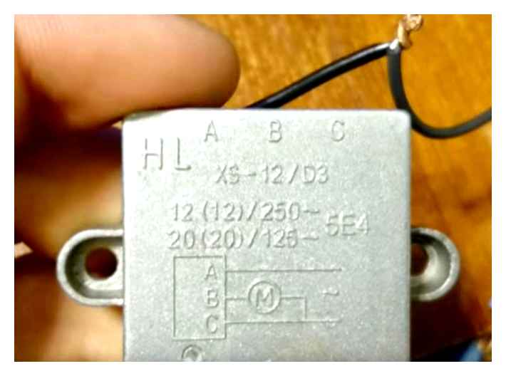
By the way be careful, there are similar devices, but with three wires. For example XS-12/D3.
Or other models that look like the KRRQD.
But they are based on a slightly different principle and must be installed after the START button, in the tool itself. They should be energized only when the angle grinder starter button is closed and immediately disappear when it is released.
Phase goes to pin “A”, zero to pin “C”. Then phase control output wire goes to the motor (this is just the third wire).
Such device will be constantly under voltage of 220 V without push-button, which is not admissible.
There is no such thing in a 2-wire unit, because it is connected in the gap circuit, and voltage (potential difference) is applied to it only at the moment of starting and operation of the tool.
Another point is the so-called electric brake or brake winding on the endstarters. It may not work with a 3-wire external controller, but it will with a 2-wire model.
Soft starter
Standard soft starter of angle grinder consists of triac, rectifier unit and capacitor set. Resistors are used to increase the operating frequency and allow current to flow in one direction. The starter is protected by a compact filter. Models have a low voltage rating. However, in our version, much depends on the ultimate power of the motor, which is installed in the angle grinder.
Diagram of a soft starter motor angle grinder with their own hands
Everyone who uses the angle grinder for more than a year, it broke. At first, every master tried to repair the sparkling grinder himself, hoping that it will work after replacing the brushes. Usually after such an attempt, the broken tool is left lying on the shelf with burned-out windings. And a new angle grinder is bought to replace it.
Drills, screwdrivers, torches, milling machines are necessarily equipped with a speed regulator. Some so-called calibration grinders are also equipped with a regulator, and conventional angle grinders have only a button on.
Low-power angle grinder manufacturers do not intentionally complicate the additional circuits, because such power tools should cost cheap. Of course, it’s understandable that the life of an inexpensive tool is always shorter than that of a more expensive professional tool.
The simplest angle grinder can be upgraded so that the gearbox and armature winding wires are no longer damaged. These problems mostly occur with a sharp, in other words, percussive start angle grinder.
The whole modernization consists only in assembling the electronic circuit and fixing it in the box. In a separate box, because there is very little space in the handle of the grinder.
A proven, working circuit is below. It was originally designed for lamp incandescence adjustment, i.e. to work on an active load. Its main advantage ? simplicity.
- The highlight of the soft starter, the circuit diagram of which you see, is a chip K1182PM1R. This chip is a highly specialized, domestically made.
- the acceleration time can be increased by selecting a capacitor C3 of higher capacity. During the charging of this condenser, the electric motor will gain speed up to the maximum.
- No need to replace the resistor R1 with a variable resistor. A 68 kohm resistor is optimal for this circuit. With this setting you can smoothly start the angle grinder with a power of 600 to 1500 watts.
- If you are going to build a power regulator, then you need to replace resistor R1 with a variable resistor. Resistance of 100 kOhm or more will not lower the output voltage. By short-circuiting the pins of the chip, you can turn off the angle grinder altogether.
- You can smoothly start almost any commercially available grinder with power from 600 W to 2700 W by putting a VS1 type TC-122-25 or 25 A semistors in the power circuit. And there’s plenty of power left over in case the grinder jams. For connection of angle grinders up to 1500 W, imported semistors BT139, BT140 are enough. These less powerful electronic switches are cheaper.
The triac in the above circuit is not fully open, it cuts off about 15V of line voltage. This voltage drop does not affect the operation of the angle grinder. But when the semister heats up, the speed of the connected tool decreases significantly. This problem is solved by mounting a heat sink.
This simple scheme has another disadvantage. it is incompatible with the speed controller installed in the tool.
The assembled circuit must be placed in a plastic box. The case of insulating material is important, because you need to protect yourself from the mains voltage. You can buy a junction box at the electrical goods store.
Screwed to the box is a socket and plug cable with plug, which makes this design superficially resembles an extension cord.
If you have experience and desire, you can assemble a more complex circuit of soft start. The following circuit diagram is standard for the XS-12 module. This module is installed in the power tool in the factory.
If you want to change the speed of the connected electric motor, then the scheme is more complicated: you set the trimmer to 100 kOhm and the regulating resistor to 50 kOhm. Or just crudely put a 470 kohm resistor and a 47 kohm diode in between.
It is desirable to connect a 1 megohm resistor in parallel to the capacitor C2 (it is not shown in the diagram below).
The supply voltage of the LM358 chip ranges from 5 to 35V. Power supply voltage not to exceed 25V. That’s why you can do without the additional DZ.
Whatever soft starter circuit you have assembled, never run the tool under load. Any soft start can be burned out if you are in a hurry. Wait for the angle grinder to unwind, and then work.
Subtleties of operation of angle grinder with self-made regulator
A limitation in the operation of the modified tool will be the strict observance of the “work/rest” mode. This is to preserve the collector winding. the collector motor gets very hot when working at a lower speed and can cause trouble.
The next factor is the moment of switching on. The RPM needs to be lowered when the tool is running. At the minimum speed the voltage might not be sufficient to spin up the rotor, the lamellas of the collector would remain short-circuited and the winding would overheat and burn out.
You should understand that installing a regulator will not increase the power of the tool in any way. If the specification specifies a maximum of 3000 rpm, the angle grinder will give a range of 0 to 3000 rpm.
This phenomenon occurs because powerful electric motors at the startup consume huge currents, which causes the voltage drop in the network. This can damage the tool itself, especially Chinese-made tools with unreliable windings, which can one day burn out during start-up.
So the soft start system will protect both the mains and the tool. In addition, a strong kickback or jolt occurs when starting the tool, which of course will not be the case with the soft start system.
Secondly, there is no speed regulator, which will allow you to work long hours without overloading the tool.
The circuit below is from an industrial design:
It is implemented by the manufacturer in expensive devices.
The scheme can be connected not only to the “angle grinder”, but, in principle, any device. drill, milling and lathe. But taking into consideration that it should be a collector motor.
It doesn’t work with asynchronous motors. You need a frequency converter.
So, we need to make a printed circuit board and start assembling.
As a regulating element, it takes a double operational amplifier LM358, which controls a triac through a transistor VT1.
So, the power link in this circuit is a powerful triac like BTA20-600.
We couldn’t find such a triac in the store and had to buy the BTA28. It’s a bit more powerful than the one in the circuit. In general, for motors with power up to 1 kW you can use any triac with voltage not below 600V and current from 10-12A. But you’d better have some reserve and get a 20A triac, they cost a penny anyway.
The triac will get warm during its operation, so you have to put a heat sink on it.
To avoid questions about the fact that the motor at start-up can consume currents that greatly exceed the maximum current of the triac, and the latter can simply burn out, remember that the circuit has a soft start, and the inrush currents can be ignored.
The phenomenon of self-induction is familiar to all. This effect is observed when opening a circuit to which an inductive load is connected.
It’s the same in this circuit. When the motor suddenly loses power, the inductive current in the motor can burn out the triac. And the snubber circuit dampens the self-induction.
The resistor in this circuit has a resistance of 47 to 68 ohms and a power of 1 to 2 watts. 400 V film capacitor. In this case, the self-induction as a side effect.
Resistor R2 provides current quenching for the low voltage control circuit.
The circuit itself is to some extent both a load and a stabilizing link. After the resistor, you can not stabilize the power supply. Although there are similar circuits on the net with an extra stabilizer, it makes no sense to use it, because the voltage on the outputs of the operational amplifier is within the normal range.
Possible replacements for low power transistors can be seen in the following picture:
The printed circuit board, which was mentioned before, is only a board for the soft starter, and it has no components for speed control. This is made on purpose because in any case the regulator needs to be wired.
Adjustment of the controller is done with a 100 kOhm multi-turn trimmer resistor.
And the main setting is already done with the resistor R5. It is worth noting that this kind of circuit would not allow adjustment from zero, only from 30 to 100%.
If you need a more powerful regulator, it can be assembled according to the following scheme:
This circuit allows you to regulate the power from almost zero, but for “angle grinder” it makes no sense.
First, the circuit is necessarily tested for performance by connecting as a load a light bulb at 40-60 W 220 V.
If everything is okay, then after disconnecting from the mains, you must immediately check the triac by touch. it should be cold.
Next, the board is connected to the “angle grinder” and a start-up is performed.
If everything works well. the angle grinder starts smoothly and the RPM is controlled. then it’s time to start the load test.
Types of motors
The motors are different in features. This means that the machine works at different speeds of the shaft that starts the machine. The motor can be:
Mainly three-phase motors are found in factories or large factories. In the home criteria are used single-phase and two-phase. This electricity is enough to run household appliances.
Operating principles
Speed regulator of electric motor 220 V without loosing power is used to maintain the initial speed of the shaft. This is one of the main principles of this device, which is referred to as a frequency regulator.
With its help, the electric appliance operates at a set frequency of motor rotation and does not reduce it. Also the motor speed controller affects the cooling and ventilation of the motor. With the help of power set the speed, which can both increase and decrease.
The question of how to reduce the speed of an electric motor 220V, many people have asked. But this procedure is quite ordinary. It is only necessary to change the frequency of the supply voltage, which significantly reduces the performance of the motor shaft. It is also possible to change the power of the motor, while engaging its coils. The control of electricity is tightly intertwined with the magnetic field and the slip of the electric motor. For such activities use mostly autotransformer, home regulators, which reduce the speed of this mechanism. But it is also worth to keep in mind that it will reduce the power of the motor.
Shaft rotation
Speed controller of asynchronous electric motor is depending on the current connection to the mechanism. The essence of the operation of an induction motor lies in the magnetic coils through which the frame passes. It rotates on sliding contacts. And when it turns 180 degrees, the connection will flow in the opposite direction on these contacts. Thus, the rotation will remain the same. But with all this action, it won’t have a suitable effect. It will take effect after putting a couple of 10 frames of this type into the mechanism.
The manifold engine is used very often. Its work is ordinary, because the current passes directly. because of this does not disappear rotational power of the motor, and the mechanism consumes less electricity.
The washing machine motor also needs a power regulator. For this purpose special boards were made, which are controlled by their own work: board speed control motor from the washing machine is multifunctional use, because when you use it lowers the voltage, but not lost power rotation.
The circuit of this board is tested. It is only worth putting diode bridges, picking up the optocoupler for the LED. With all this still need to put a triac on the radiator. In general the adjustment of the motor starts from 1000 rpm.
If you are not satisfied with the power regulator and its functionality is not enough, you can make or improve the mechanism. To do this, account must be taken of the amperage, which must not exceed 70 A, and the heat loss when using the. Therefore it is possible to install an ammeter to adjust the circuit. The frequency will be small and will be determined by the capacitor C2.
Next you need to adjust the speed controller and its frequency. At the output this pulse will go through a push-pull amplifier on transistors. You can also make 2 resistors which will serve as an output for the cooling system of the computer. That the circuit does not burn out, you need a special blocker, which will serve as a double value of current. This way this mechanism will work for a long time and in a suitable volume. Power controllers will give your appliances a long and long life without much cost.
Thyristor-based device
In this model, shown in Diagram 1, 2 thyristors are used, switched in counter-parallel, although they can be changed with one triac.
Scheme 1. thyristor speed control of collector motor without loosing power.
This circuit regulates with the thyristors (triacs) opening or closing at phase-neutral transition. For the correct control of the collector motor use the following methods of circuit modification 1:
- Installation of protective LRC circuits, consisting of capacitors, resistors and chokes.
- Adding capacitance to the input.
- The introduction of thyristors or triacs, the current of which exceeds the nominal value of the motor current in the spectrum of 3.8 times.
This type of controller has advantages and disadvantages. The first are low price, small weight and dimensions. The second should include the following:
- Use for small power motors;
- Noise and jerking of the motor occurs;
- When using a triac circuit, there is a constant U on the motor.
This type of regulator is put in fans, condensers, washing machines and electric drills. Great at doing its job, despite the drawbacks.
Constructive features
Asynchronous motor has no distinct poles, unlike an electric motor of unchanging current. The number of poles is determined by the number of coils in the windings of the fixed part (stator) and the connection method. The asynchronous machine with 4 coils has a magnetic flux. The stator is made of special steel sheets (electrical steel), reducing to zero eddy currents, in which significant heating of the windings occurs. It leads to a massive inter-turn short circuit.
The iron or rotor core is pressed directly onto the shaft. There is a small gap between the rotor and the stator. The rotor winding is made in the form of a “squirrel cage” and made of copper or duralumin bars.
READ Cut-off saw from angle grinder with your own hands
In motors with power up to 100 kW aluminum is used, which has a low density. for the filling in the grooves of the core of the rotor. But despite this construction, these motors heat up. To solve this problem we use fans for forced cooling, which are mounted on the shaft. These motors are ordinary and reliable. But the motors consume a large current at start-up, 7 times the rated current. Because of this they have a small starting torque, because most of the energy of electricity goes to heat the windings.
Making the soft starter
The circuit is assembled on a circuit board with the dimensions of 45 x 35 mm, the board is as compact as possible, so it can be built into the body of the tool, which requires a soft starter. It is better to solder the power wires directly to the board, but if the load is small, you can install terminals, as I did. The board is made by LUT method, photos of the process are shown below.Download the board:
It is desirable to tin the tracks before soldering the parts to improve their conductivity. You can put the chip in the panel and then it will be easy to remove it from the board. First you solder resistors, diodes, small capacitors, and then the largest components. After completing the circuit board assembly it is absolutely necessary to check the correctness of its mounting, test the tracks, wash off the remaining flux.
Making a soft starter socket
The most important requirement for such an outlet is its mobility. That’s why you will need a portable.
With it, you will be able to smoothly run the tool anywhere. in the garage, in the cottage, when building your house on different parts of the construction site.
The first thing you need to do is to disassemble.
The main power wires in it can either be soldered or connected by screw terminals.
Depending on this, so will the connection of your additional socket. It should be just an extra socket near the carrier to be able to connect the tool in different modes at the same time.
By the way, if you by mistake include an angle grinder or circular grinder, having a factory built-in soft starter in the socket, also equipped with such a controller, then surprisingly everything will work. The only moment. you will get a delay of start of saw or disk revolutions for a couple of seconds, which is not very convenient in operation and without a habit can puzzle.
Here are the real tests of this connection, made by one master from YouTube BaRmAgLoT777. His comment after trying it out on a Dremel type engraver, a Bosch drill, a Makita router, an Interskol circular saw:
Next, for the assembly of the outlet take a stranded copper wire section of 2.5 mm2 and stripped its ends.
After that you need to tin the contact pad on the adapter, where this wire will be soldered.
Securely solder the cable cores to these pads.
Carefully lay the wires and cover the extension cord.
Take a square outdoor socket for installation on the outer surface of the walls, and in its housing try on soft starter unit. Since it has compact rectangular dimensions, it should fit in there without too much trouble.
You mount and fix the body of the socket on the same platform with the extension cord.
Connect the sensor unit in the gap of any wire, phase or neutral. Do not mix it up, it does not have a phase and a zero at the same time, i.e.е. 220В.
It is installed on some one of the wires.
Also for this BPP, it makes no difference which side is the inlet and which side is the outlet. The strands are soldered and insulated with heat shrink.
After that, all the insides of the socket are collected in the case and it only remains to close the whole construction with the lid.
At this point the whole remodeling of the carrier and making a socket can be considered complete. In time it will take you no more than 15 minutes.
Soft starter controller for the machine with his own hands
Greetings, DIYers! And today we have a small home-made device, which will make any self-made machine more convenient and safe. The author of this homemade device is AlexGyver.
It all started with the fact that the author began to use the drill stand more often, as not always possible to drill a hole perpendicular to the surface of the workpiece. In this stand is a cheap drill without built-in speed regulator, and in the simplest case, to work this thing you need to squeeze the trigger and put on the latch, but it is already at almost all the drills.
And the problem is actually the maximum rpm is too high even for drilling aluminum, not to mention stainless steel and other hard-to-drill metals and alloys. As for the convenience of turning it on, the drill can be left on with the button depressed and turned on with the button on the socket. Convenience is questionable, and immediately give the maximum power is also not very cool for the motor, not for the drill, not for the construction of the rack. That is, not enough soft starter. But if you take, for example, a homemade drilling machine with a powerful motor and a heavy rotor, it just needs a soft starter. For control of a non-three-phase motor, which is here, a triac and a simple circuit will be enough.
If you, like the author, do not like soldering chips, the Chinese have ready-made triac dimmers for 3 kW of power.
If you connect a drill through it, you get the speed control. The link to such a dimmer the author left in the description below the video (link SOURCE at the end of the article). It costs a few pennies, it’s much cheaper than assembling it by components in our stores. If you only want to have a drill stand, it is easier to get a drill with a power regulator for it.
At the very beginning the author set a goal to assemble a device which will perform the following functions:
Smooth motor start, with adjustable acceleration time; 2. Acceleration to the set value, which is limited by the potentiometer, i.e. the knob; 3. With the same knob you can change RPM during work; 4. The start will be from a logic button that has a voltage of 5V, which means the button will be safe for wet hands, and may be small and weak; 5. To start the machine, the button will need to be held for some time. That is, with a random click the motor will not start.
You can assemble such a machine controller on analog components, but unfortunately the author doesn’t know anything about it, and offers to implement all the functions mentioned above on the microcontroller. And of course the circuit will be 10 times easier. As a microcontroller, we will have a platform arduino nano. It costs 150 bucks from the Chinese.
Also this project can be run on a Digispark board, which costs about 100. The circuit board runs on 5V, you can power it from a USB charger for a smartphone, but the author is planning to make a compact device. So he decided to use this mini power supply.
Next we need a 10 kOhm resistor and a small button. And actually we need a power part, which will supply current to the motor.
The circuit is soldered in 15 minutes on a breadboard. Also, for those who don’t like to solder the schematic, the Chinese have a ready-made board with the same circuit, but it is unfortunately huge and we won’t use it.
Now we need to download the firmware and load it into the board. Using the link in the description under the author’s video, go to the project page and download the archive.
Next, using the mega detailed instructions there on the author’s website, we load the firmware into one of the two boards. They work in exactly the same way. In the firmware is the only setting we are interested in. this is the time to reach full power (in milliseconds).
Now let’s assemble the schematic and see how it all works. Two circuits of course, for different boards.
Soft starter controller for a machine tool with my own hands
Greetings, DIYers! And today we have a little homemade, which will make any homemade machine more convenient and safer. The author of this firmware is AlexGyver.
It all started with the fact that the author began to use the drill stand more often as not always possible to drill a hole perpendicular to the surface of the workpiece. In this stand is a cheap drill without built-in speed regulator, and in the simplest case, to work this thing need to clamp the trigger and put on the latch, and here it is already at almost all drills.
And the problem is that the maximum speed is too high even for drilling aluminum, not to mention stainless steel and other hard-to-drill metals and alloys. As for the convenience of switching on, the drill can be left on the clamped button and turn on the button on the socket. The convenience is questionable, and immediately give the maximum power is also not very cool for the motor, not for the drill, not for the construction of a rack. That is, it lacks soft start. But if you take, for example, self-made drilling machine with a powerful motor and a heavy rotor, he soft start is well needed. For controlling a non-three-phase motor, which is what you have here, a triac and a simple circuit will be enough.
If you, like the author, don’t like soldering, the Chinese have ready triac dimmers for 3 kW of power.
If we connect the drill through it, we get control of revolutions. The link to such a dimmer is left by the author in the description below the video (link SOURCE at the end of the article). It costs a few pennies, much cheaper than assembling it by components in our stores. If you only want to build yourself a drill stand, it is easier to get a drill with a power regulator.
At the very beginning the author set himself a goal to assemble a device that will perform the following functions:
Soft-start motor, with adjustable acceleration time; 2. Acceleration to a set value, which is limited by the potentiometer, i.e. the knob; 3. You can change the speed with the same knob while working; 4. The start will be from the logic button, which has a voltage of 5 V, so the button will be safe for wet hands, and it can be small and weak; 5. To start the machine, you need to hold the button for a while. That is, from a random click the motor will not start.
To assemble such a machine controller is possible on analog components, but unfortunately the author is not versed in it, and offers to realize all mentioned functions on microcontroller. And of course the circuit will be 10 times easier. As a microcontroller, we will have a platform arduino nano. It costs 150.
Also you can run this project on a Digispark board, which costs about 100 bucks. The board works on 5V, you can power it from a USB charger for a smartphone, but the author is planning to make a compact device. So he decided to use this mini power supply.
Next we need a 10 kOhm resistor and a small button. And actually you need a power part, which will supply current to the motor.
The circuit can be soldered in 15 minutes on a breadboard. And especially for those who don’t like to solder the board, the Chinese have a ready made board with the same circuit, but unfortunately it is too big and we won’t use it.
And now we need to download the firmware and load it into the board. Using the link in the description under the author’s video go to the project page and download the archive.
Next, using the mega detailed instructions on the same site the author, download the firmware into one of the two boards. They work in exactly the same way. The only setting we are interested in in the firmware is the time to reach full power (in milliseconds).
Now let’s make a circuit and see how it all works. There are two schemes of course, for different boards.
What soft starter to choose for power tools
You can buy the PSA module in specialized stores or online stores. In recent times, most consumers order such soft starters for their tools from a popular Chinese online resource called Ali Express.
As a rule, PSA are installed on power tool models that are equipped with electric motor of increased power. Most often, the soft drive system is equipped with such power tool as an angle grinder. However, in this case, if necessary, the user can buy a special soft starter module and install it on any power tool, which is at his disposal.
When choosing such a module, first of all one should take into account the nominal value of the starting current necessary for work, starting the electric motor. Simply put, when choosing such a device, you should first of all take into account the power indicators of the electric motor with which the tool is equipped. In addition, when selecting a controller, it is desirable to determine the time required to start, as well as a full stop of the electric motor. It is also desirable to pay attention to the dimensions of such a module and to study its connection scheme in advance.
Besides, soft starter modules are available with two and three outputs. Models with two outputs are more convenient and practical, but they are less durable than counterparts equipped with three outputs. In addition, a module with two outputs is quite possible to install on the carriers, to which you can then connect a variety of equipment.
How to install
It is not difficult to install a soft starter or soft starter on a power tool yourself. To do this you must first disassemble the handle of the power tool where the starter button is located. Then remove the contacts from the switch and connect the module in the gap between the motor and the start button. The output of the controller must be connected to the electric motor. All contacts should be connected to each other with a soldering iron, and then insulated.
You can also twist the contacts together and insulate them with heat shrink tubing or simple electrical tape. At the final stage of assembly, the power cord is reconnected to the power tool, and the body from the handle is placed in its original position.
In addition, if desired, each user can make his own soft start system using a special board KR1182PM1R. To make such a device at home, you will need to buy materials and components such as:
The electronic diagram of this unit can be found on the Internet. The main element in this softstarter is the circuit board. For the power part of this unit are triacs. The main advantages of this unit are such as ease of use (no need to further configure the controller after its final assembly), fits any tool that runs on 220V AC power.
If necessary such a unit can be installed into the equipment or can be connected to the point of rupture in the power cable. It is best to connect such a controller directly to the socket that will eventually power the equipment.
Assembly of the device
You can put any other units you have and which suit your needs in terms of power, but you should consider that the more powerful triac is, the less it will be heated and, therefore, will work longer. Depending on the load you should also use a heatsink for the triac.I put BTA41-600. You don’t have to put a radiator for it. It is powerful enough and won’t get warm in short term work with a load up to two kilowatts. I just don’t have a more powerful tool. If you plan to connect a heavier load, then think about cooling.Let’s assemble the parts for assembling the device.
It is a good idea to cut the breadboard to size with a pair of large scissors. Cut easily, simply and neatly.
Mounting components on the breadboard. It is better to solder a special socket for chips. There is no risk to overheat the pins of the chip, you don’t have to fear the static electricity and if the chip burns out, you can replace it in a couple of seconds. It is enough to take out the burnt out one and insert the whole one.
Checking Operation
Checking the device in operation. Carefully! All circuit elements are under direct 220 volt power supply! Life-threatening! Finish assembling the device.
In order not to confuse this device with a simple extension cord, it should be marked in any way. I did it with a self-adhesive price tag and some masking tape.
Please watch the video of the test of this device. A visual demonstration of the change in the behavior of the device at startup. Good luck with your business and worries.