Table for a hand router with their own hands
A step towards the professional workshop
Many craftsmen adapt an ordinary workbench as a router table. However, it has been proven in practice that it is better to have a separate, specialized design. The explanation is simple:
- Vibration will occur during operation and may cause parts to be unstable on the workbench;
- To move up and down will require a special device (elevator). There is often not enough space in a usual workbench.
An important feature of the router is the need to install a support plate, associated with the table top. For it use metal, plexiglass or strong plywood. The fixation is done by means of holes
Most hand tool manufacturers provide fasteners for their products in advance, assuming that a significant portion of their products will also be used in a stationary version
The fixing is done with the help of holes. Most hand tool manufacturers provide fasteners for their products in advance, assuming that a significant portion of their products will also be used in the stationary version.
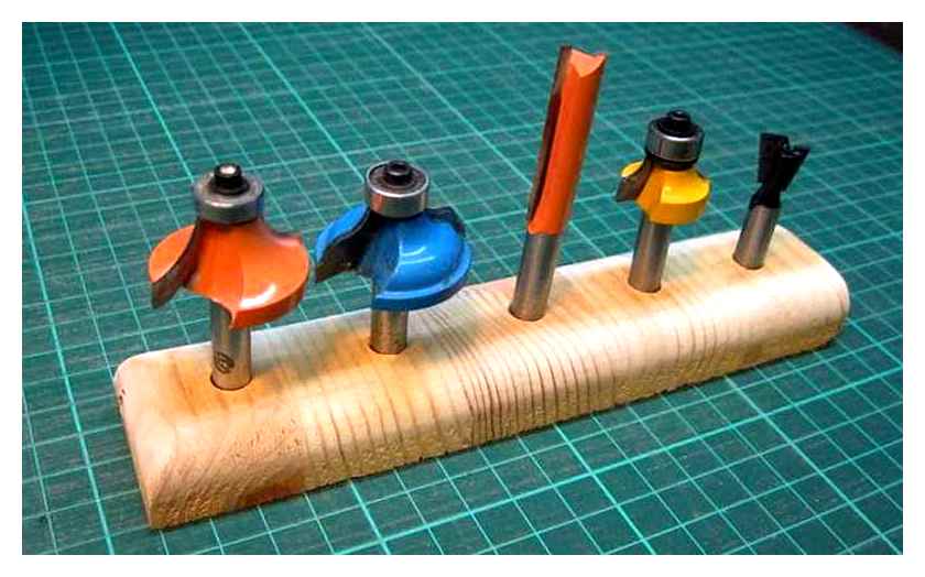
Different milling cutters are used
Methods of milling using different types of shaper cutters
Based on a study of known designs, a number of basic requirements for a milling table are formulated.
- Base plate must be in one plane with the table. When moving the workpieces to be machined, vertical displacement on the support is not allowed. Some craftsmen leave the basic sole. Bring it “zero” to the table top. But most agree that a different plate should be made.
- For convenience and safe use of the machine, the on and off buttons should be positioned so that they can be used quickly. It may be necessary to urgently switch off the motor power.
- Workpieces to be machined can be moved relative to the stop. It can be offset so that the craftsman has the opportunity to mill edges as well as grooves in semi-finished products.
- It is useful to consider where to set up the machine. It needs to be easily accessible. May have to mill a long jointer. Then the workpieces must be stacked on both sides of the table.
- Some craftsmen adapt the installation of only the table top to an existing machine. In this way it is possible to combine several devices on a single bed.
Even an ordinary table can be turned into a machine tool. An example of such a conversion is shown in the video.
To get the most out of the machine, minimize the thickness of the base plate. Then the outreach of the cutter will be maximum. Long finger milling cutters for deep milling can be used in practice. Only fairly rigid materials will provide durability.
Mounting the vertical travel device
The movement of the hand router up and down is made with a device called an elevator. Here a variety of mechanisms are used to move and fix the set position.
A possible variant of the elevator is shown in the video.
Milling machine for home
Woodworking machine is quite expensive if you buy it directly from the factory, so few people could afford it. But if you look at the other “side of the coin”, then having a milling machine at home is quite cost-effective. For this reason, often many ordinary people working on these machines and craftsmen with a lot of experience come to the realization that: “You need to make a milling machine yourself, with your own hands!” and they think correctly, because it is quite possible and not so difficult.
What knowledge do you need to possess in order to build a wood milling machine with your own hands?
People with experience with machine tools give a recommendation: It is necessary first to learn what these machines are made of, to understand the circuit of the milling machine, before starting to assemble.
Table for a hand router
I think that those home masters who have a hand router, but do not have a table for the router have not once thought about how to buy or make a table for the router. Since using a router stationary, the convenience of working with it greatly increases, especially when working with small elements.
But for a home workshop table is often not justified, both for financial reasons, and, for example, as I have in the occupied space of the apartment. Therefore, as an option, you can use a small homemade milling table, which is attached to a universal workbench or even an ordinary table.
Clamping devices and elevator
Tables for the router can also be made, using clamping devices. The router is installed into a tabletop, with a shallow drilled hole. The diameter of the hole is equal to the size of the router base. router mounted in three clamping fixtures.
The advantage of such a method is considered to be the quick assembly and disassembly of the cutter. However, there are a few drawbacks. First of all, this is due to the limited diameter of the hole for the tool, so you have to use only cutters of a particular size. It is necessary to look under the table all the time when setting the router at a certain height.
An additional element that a milling table requires is considered a universal plate.
This detail is used by all routers equipped with a built-in elevator. The main advantage of this router is the motorized elevator. As a result, it is possible to adjust the height of the tool above the main table surface. The motor can even be lifted in order to change the milling cutter.
Before buying such a plate, it is important to know a few nuances. First of all, the installed elevator will be an obstacle to the installation and removal of the router. An elevator is always an added weight. Very expensive elevator elevator, but it will provide more accurate production of parts.
Mini Circular (Sawing) Machine. Desktop. Portable. Portable
Hello, I want to welcome everyone who is interested in the world of DIY! In this article I will show how to make with their own hands no tricky, compact mini circular saw, from improvised materials, which runs on battery power, and from the network, with adjustable and tilting saw, with a simple transportation system.
There will be no intricacies in terms of material. Leftover scraps of floor laminate after repairs, that’s what my mini saw machine will be made from. And here’s something that didn’t fit in this post.
As the basis of the project took the motor RS-550, which had long been lying in the backcountry, from what, now I do not even remember. Found the marking of the motor on the Internet: RS-550, DC 6V-24V, 30000 rpm, as the motor itself is absent any inscriptions.
Tools and materials that were used in the making of the homemade machine:
Motor guard with blade outreach adjustment function
I sat, thought and decided, if my machine will be the mechanism for adjusting the lift and tilt at 45 degrees of the saw blade, then you need to invent and implement a mechanism for lifting and tilting.
This mechanism was invented, it remains to implement the idea. For this purpose it was necessary to make two bodies under the motor with a saw blade. That one would move up and down, and the second to the side and saw along, that is deflected by 45 degrees.
I found in my the cover of an old PC case. The metal is very soft, easy to bend and machine. Cut out with scissors on metal, something like a protective casing for the motor.
Then I made holes for the hot air outlet, bent the part around the circumference of the motor and drilled holes for mounting.
Then I took a metal plate, bent it under 90 degrees and drilled holes for mounting. It will be the base of this part of the structure.
After that I took an aluminum plate and made it into two identical parts for the sliding mechanism of the saw blade departure.
To seal the motor housing I cut out a pad, from the backing material, such packages in aliexpress.
To install the saw blade to the shaft of the motor used the adapter adapter for 3.17 mm, which I ordered from aliexpress.
Now let’s assemble this part of the structure. We put the motor in the semicircular metal part of the body.
Screw the aluminum plate to the front of the motor, gripping the metal part in your hand so it doesn’t bend.
Install the second guide plate with screws to the bottom plate, which is the base of this part of the sliding mechanism. I made this beforehand.
Fixing the base to the semi-circular metal part of the body with small screws.
This is how the assembled machine unit looks like from the front side.
Rear view. I almost forgot to mention, in the semi-circular part. cover was threaded for m2 screws.
Movable motor housing for saw blade tilted by 45 degrees.
Sawed all the parts, for the outer body for the saw tilt, out of laminate.
This is the front wall of the tilt housing on the side where the saw blade is located. Sawed arc slots of different sizes, so that the inside of the mechanism could move up and down. Also drilled a hole for the axle on which the internal unit with the motor will be standing.
Vacuum chamber with my hands
I want to share my version of how to make a vacuum chamber with my own hands.
In my opinion this is the easiest way without any drilling of holes, installation of additional fittings and taps. You will need an empty bottle of Freon, Plexiglas, self-adhesive tape for ventilation, plasticine, epoxy resin. The bottle can be purchased for a bunch of oranges from the air conditioning installers, as a rule it is thrown away.
Cut the bottom of the cylinder with an angle grinder. We turn the cylinder, it is now the top of the chamber. Now we need to create the plane where the lid of the chamber will be put in the future. For this purpose around the cylinder top create a molding of plasticine, then pour the resin. After pouring the resin, we get a flat surface for the lid. The lid I made from an old aquarium, cutting a circle the diameter of the circumference of the cylinder and gluing it with self-adhesive tape. The lid fits tightly and during evacuation you can’t open it even with a great effort, until you open the tap from below.
The good thing about this chamber is that it already has a valve which shuts off the air supply and there is a fitting for hoses. It is necessary to drill a valve inside because the holes there are very small and it will be difficult to supply air into the chamber during evacuation.
The gauge station can be purchased with a single gauge to save money.
How to make a router table for a hand router by yourself
The router is a unique tool with a wide range of functions. It can process wood, plywood, chipboard, even aluminum. With its help it is easy to drill holes of any diameter, cut complex shapes, make groove connections of parts, cutting letters and patterns.
Homemade wood and plywood construction
Why do you need a router table?
To work on the cutter requires its firm fixation to the surface from a metal plate attached to the stationary table. After all, it is more convenient to work with a rigidly mounted tool than to hold it in your hands. The purpose of the cutter: figured processing of edges, slotting. It can be used for working any types of wood slab, drilling holes of different depths and diameters.
Moving the workpiece across the worktop is much more comfortable than holding the tool in the air. Fine-tuning your cutters helps increase the accuracy of the lines you draw on the parts you’re working on.
For reference! Online stores offer a wide selection of milling tables. Especially a wide model range with full equipment is presented by the German company Bosch.
You can buy a milling platform or try to make one yourself out of fiberboard. A homemade table will cost much less than its industrial counterparts. The following is a look at how you can make a table for a milling machine at home.
Table for a hand cutter with your own hands
Usually to perform some new work, new tools are required. As a programmer, I am very familiar with this, because for many years I have had to create libraries and write utilities for every new task. These are the very tools with which the solution of the following tasks becomes easier and simpler. Probably so in many areas, except for those where you have to create everything from scratch, using only knowledge and skills. (Maybe that’s why I don’t like to paint, for example, that I’m used to using previous workmanship).
I finally finished my router table. (It took me 7 evenings to create it). At first I thought to buy ready made, but the ones I found for affordable money and suitable for my work. I wasn’t at all satisfied with. And I decided to make it myself under the hand mill, which I had a Kalibr FE-650E.
Milling table. a very useful handicraft tool. I’ve never really thought about it before, but if you look around any house, you can see a lot of things which have been milled: window frames, furniture doors, picture frames, wooden skirting boards, door casings, overlays, etc.
I will not bore you, describing the entire manufacturing process. I will just show you from all sides and note the main interesting points.
First I modeled it in 3D, as usual. I did not copy anyone else’s table, but developed the model for myself, having seen a lot of ready-made similar milling tables on the Internet. The idea is common, the essence is the same, the details are different, t.к. Everyone realizes it for himself, using what he has and what he can.
Т.к. My workshop is small. The table also turned out to be small: the top of 60×40 cm, the height of 35cm (together with the corner stop. 45 cm). Fits nicely on one of my shelves. (It is easy to take it out, use it and put it away). The table top and the side support are made of 15mm laminated plywood. On the table top, I cut three rails for sliding various attachments.
The side fence has slots, can move back and forth, and is locked in position with two thumbscrews. The angle fence is connected to the chip evacuator. (the routing cutter produces a lot of chips when working) if necessary. it is easy to remove the side support and replace it with other attachments or do not attach anything at all.
For solidity and stability the legs are made of 22mm chipboard. The front base panel covers the “guts” while still giving you access to the parts you need. Example: No separate power button is needed for this cutter model as is common on router tables, i.e.к. Access to the cutter itself is convenient as well.
The table legs are purposefully set back from the edge so that you can use clamps to attach something extra. (clamps, stops, templates)
The stop has two flaps that can extend and slide, depending on the size of the cutter. The position of each flap is fixed with wing bolts.
This router model is very convenient in that the router can be easily removed from the base frame. And, by removing it, it’s easy to change cutters.
A normal vacuum cleaner hose is connected to the chip extractor.
Under the table. simplicity and minimalism. 🙂 Chips are sucked out from above through the side stop and from below through the chip evacuation of the cutter itself.
The chip evacuation is very effective. Almost all chips and dust are vacuumed without littering the room.
This cutter model does not have fine depth adjustment. You had to put pressure on the router and catch the desired depth with a clamp. (I should note that this is terribly inconvenient. You have to put a lot of effort in rearranging the depth to get to the right one)
Finished the base by adding the so-called “elevator”.
Drilled the bed and installed the regulating screw with a high nut (in the picture in the center). By tightening the nut, you can smoothly adjust the depth.
Parts and materials for table manufacturing
The next step in the fabrication of the table for the router is the selection of materials. The best material for the table top is multilayer laminated plywood. The optimal thickness for the table top is 40-45 mm plywood. If you do not have one, you can use laminated chipboard or try to glue a tabletop from two layers of plywood 20-25 mm thick.
This thickness is necessary so that the load on the work surface, regardless of the type of motor tools do not deform the table top, because the main unit will be mounted on it.
- 15-18 mm thick plywood for the side posts and crossbars;
- wooden bars 45×45 mm or 40×50 mm to strengthen the frame;
- A metal plate for making a plate for the router;
- self-tapping screws 25 and 45 mm;
- Furniture corners to reinforce the structure;
- furniture bolts and wing nuts. for fixing the limiting board;
- safety button, socket, wire and plug;
- duct tape and heat shrink tubing.
Preparing parts
After marking the parts, cut out all the necessary parts, mark the points of attachment, the places of installation of metal corners.
In the table lid, a landing place is cut out for the tool, and a cut-out is made for installation of a milling plate. Glued, if necessary, halves of the table top and clamped. The frame is assembled, and the details of the router mounting unit.
Installation of the router on the table
After the table top dries, the milling plate is installed on it and the router mounting unit is attached. All parts are attached with screws, but not fixed firmly. In the process of assembling it is necessary to ensure that the table top is placed horizontally. At this stage it is important to set the tool perpendicular to the surface of the table top. When the necessary precision is reached the screws are pressed completely and the cover with the tool is installed on the table.
After the cutter is set into the table, the plate is inserted and the stop bar is set. The last step is the installation of the emergency button and the rest of the electrical equipment. plugging, socket, fixing the trigger on the tool.
As you can see to make a milling table of improvised materials with their own hands is not very difficult. The construction, the materials and tools used do not require deep knowledge and special skills, so that even a novice can do this construction.
Arsenal Wizard R’s FanProject 2021
The Festool MFT /3 has not in vain gained popularity around the world among craftsmen working both in workshops and outdoors. MFT. Multi Function Table. is a combination of mobile desktop and workbench. In the review photo and video gallery, the specialists of Arsenal Masters R made a selection of photos and refinements, improvements, fixtures and homemade versions of the table Festul MFT.
Overview photo gallery “Arsenal Masters RU”: workbenches of Japanese and European type and mobile workbenches of German manufacturers, etc:
In this photo review we have gathered and decided to show the most different ideas and implementations of the Milling machine, from simple table machines to full-fledged multifunctional solutions:
What accessories and materials are needed in the work
To create the power components, steel angles and pipes with a minimum wall density of 2 mm are used. Their connection options: welding or screws. All metal components are coated with primer and paint to be protected against corrosion.
For worktops and some other elements, durable grades of particleboard and plywood are suitable. They are resistant to moisture, temperature fluctuations and other hazards.
Electric motor
It is needed when you plan to create a small CNC router. Its most important parameter is power. It is better to use a machine for 1100 watts. It will allow the use of a variety of cutters.
You can also use a motor from handheld electric tools like drills, rotary hammers or angle grinders.
Motor type
For optimal performance, you can base the machine on an asynchronous unit with three phases. Then the milling machine will be connected to the network, guided by a special circuit. It has a “star-delta” algorithm. This ensures that the motor starts smoothly and allows the machine to work at maximum power.
If such a motor is connected to the network with one phase, it will lose 50% of its efficiency. If the network does not allow for this kind of connection, then use a 1-2 phase motor.
How to make a wood lathe with your own hands: drawings and technology
The easiest way to make a tool at home with your own hands is to construct a lathe or milling machine from a drill or an electric motor removed from another tool. This process is not so complicated, so every master is able to cope with its implementation. It will require an electric motor, the power of which does not exceed 500 watts, and improvised materials. A drill can also be used as a drive. Of course, to make a lathe will require some skills.
Arrangement of the tailstock of a homemade wood lathe
The following elements are needed to build the machine:
It is useful to have a drawing, which will help to orientate the dimensions and correctly manufacture all elements of the construction for its subsequent assembly.
How to make a homemade drilling machine with a motor with your own hands
First you need to prepare the shaft of the electric motor. To do this, the faceplate is mounted on it, a steel center with a thread will do. The second center is mounted in the tailstock tube. To make the frame you will need a pair of angles 5×3 cm, their length. 15 cm. The motor is bolted to the frame.
Example of a homemade drilling machine
In the next step of making a homemade machine with their own hands, the assembly of the headstock is performed. This element is formed from a pair of horizontal and a pair of vertical angles. The tube intended for the spindle is attached to it. A bolt with a diameter of 1.2 cm needs to be inserted into it. Its head should be sharpened at a right angle beforehand. That is how the central part of the spindle is marked. After that, the headstock is mounted on the bed. On the upper post, which connects to the horizontal corners, it is necessary to fix by welding a tube.
To make the fork you need to take a steel rod with a chamfer. Also this element should have a hole, which will be used to fix the support ruler. It is necessary to weld a tube with a locking screw vertically to a long angle. Then the undercarriage rod is inserted into it.
As the spindle of the headstock will be used motor rotor, on which the faceplate is mounted. Several holes must be made in it. The fork will be inserted in the central part. The holes on the edges are designed to fix the part with screws.
Even with the help of simple tools you can create interesting wooden products, for this you need to learn the technology of working with the tool and practice
How to make a wood lathe with your own hands from a drill
If you have at hand a workbench with a solid and flat work surface, you can build a lathe without having to build the frame. An electric drill will serve as the rotary drive and the front headstock in this case. According to the simplest drawing of the machine, this tool is enough to fix on the surface of the workbench through the neck. Clamps and a clamp are suitable for fixing.
Next, you need to make a stop, which will act as a tailstock.
This element is mounted in front of the drill. To create it, you can take two bars of wood and a regulating screw, sharpened at one end under a cone. If you intend to use the machine for processing solid wooden workpieces, it is desirable to fix the stop on the table with the help of clamps.
To make a tool with their own hands enough inexpensive materials. A drill-based lathe can be used for turning various parts:
Using a workbench with a solid and flat work surface, you can make a lathe from a drill with your own hands
Extend the functionality of the tool by adding attachments and other features that can improve the quality of your work.
Such improvements include:
- performing winding on transformers;
- application of dyeing compound over a rotating part to create patterns;
- making spiral notches on the workpiece, etc. п.
Installation of a special attachment in the form of a gauge allows using the machine for making a whole series of identical details or products according to the template.
Example of a multi-functional homemade woodworking machine from a drill